Sunday 1 December 2013

Waterproof temperature sensor housing

I had some plates made at work. They are 60mm x 60mm x 10mm copper that is then tinned via electroplating. The electroplating is to stop a layer of copper oxide forming on the surface and acting as an insulator. Between each layer I have inserted a gasket made from a bicycle inner tube. The hole in the middle is 18mm and is the cavity in which the LM35 temperature sensor and an LM358 op-amp with appropriate resistors (270k / 27k) for setting the gain (1 + 270/27 = 11).
I tested it for waterproof and all went well.

Sunday 17 November 2013

We have ethernet

A bit of chopping and soldering and I have an Ethernet socket on the NXP. The chopping was an old D-Link 530-tx network card. I also discovered it has an 93LC46 1024-bits serial electrically erasable prom on it. That could be an interesting device one something sometime. It's not even had its legs trimmed off so it will go in a 8 legged socket (although I snapped a leg off de-soldering it!

Thursday 14 November 2013

Solder on

That's the bulk of the soldering done. The 5v voltage regulator, the Nand Gate and L293D Half-H Drivers are in position. The control lines from the NXP are soldered in with a ribbon cable socket, the 3.5mm jacks for 12v outputs and a 3.5mm jack for the 12v supply are all in place. I added the extra GND line to make the D-Sub 16 lines. It didn't all work first time because a tiny sliver of solder was connecting the 5v rail and the enable line. Took me a while to find it but the fact that I did intermediate testing meant I knew it was the newest soldering I had to re-inspect. I could really do with better inspection equipment - the light isn't bright enough and maybe a magnifying lens or camera would be a benefit.

Here it is with the NXP up and running. The PSU star connector is 12v in.

Tuesday 12 November 2013

Regulation

I have decided to go with a single 12v power supply instead of the dual 5v / 12v I was using. I needed a regulated 5v for the Atlas Scientific sensors so I rolled it all into on. The 12v goes into the control board and thr CPU can take the 5v Vcc from there up the 15-Way D-Sub. I've still got a problem because added the temperature sensor means I need 16 channels! So I'm going to have to think my way round that. Worst case I shall use the shell of the D-Sub as an extra pin and link that to Gnd.

I've added the 5v regulator to the board. I don't know how many amps I will be drawing to run the semiconductors. I hope it's not much because it is that current times approx 7v that I will be dumping out of the regulator. The regulator is maxed at 1.5A anyway so at most I will be dumping 10.5W and only consuming 7.5W ! I'm pretty sure that 1A is unlikely. If it becomes an issue I can go back to split supplies but I bet they do the same. The light I want to use for a 3ft sqr grow is 250W so it's a small proportion. Perhaps I can water cool it :)

Here's the circuit without ICs and just a regulator

I have tested the 5v rails and they are registering 4.9v on the multimeter, unloaded. My Multimeter is cheap so I don't know if it is out of calibration or the regulator is only producing 4.9v. No matter. It is more important to have a constant voltage than an exact one.

Monday 11 November 2013

Temperature and op amps

As I said, turns out the conductivity sensor has no built in temperature sensor is in, which is a pain as I have to make a waterproof thermometer. No matter, I have the sensors - LM35. My LM358 Op Amps arrives (5x) and with them my 5v regulators L7805CV.

Even though the function for calculating the gain of an op amp is easy Vout / Vin = 1 + Rf / Rg, finding resistors from the box of resistors you have takes a bit of time.

I ended up choosing 2 x 270k for Rf and 55k for Rg. I don't know if 2 x 27 and 5.5 would be better. But I ran it in the Livewire simulator and it worked so we'll see.

Now I have the regulator I am going to include that too.

As usual the circuit is online. http://www.circuits.io/circuits/6588

G = 1 + Rf / Rg = 1 + (270k + 270k) / 55k = 540k / 55k = 10.8182

Using this ratio we can see that we top out at just over 30 ° C. An unlikely value for a tank of water in the UK

A quick test with that circuit and I get 1.5v in my nice cosy house.

° CLM35: 0.01V per ° CLM358: * 10.8182
00.000.00
50.050.54
100.101.08
150.151.62
200.202.16
250.252.70
300.303.25

Now the problem I have is how to make this :

waterproof!

Wednesday 6 November 2013

Knocking some sense into it

I finally got the Atlas Scientific conductivity sensor all wired up.

Turns out I have slightly misunderstood the documentation which says "temperature corrected reading". But it turns out you have to tell it the temperature and then it responds with an adjusted reading. Luckily I have a bag of LM35 temperature sensors. Of course, this does give me the problem of making it water proof but that should be too much trouble. I could be doing without the added complexity but hopefully it's not too much to extra. The datasheet says that its output is 0 mV + 10.0 mV/°C

The analogue in pin on the NXP is in the range 0-3.3v so if we use that raw it is the range 0-330°C which is an order of magnitude away from perfect, so I'm going to have to add an op-amp, they are only £1.88 for 5! I'm actually a little bit excited about this :)

The test code, as usual, is on my account at mbed.org

I have written code to read the sensor, and pump readings out to Ethernet when ready. It is time for bed so this will have to wait until a suitable time. I also need a stable5vsupply for the sensor so I have ordered so 5v regulators too, I think I have a couple of 5v zeners for now.

Sunday 3 November 2013

Time to start soldering

The breadboard design testing phase is over. I'm confident I can commit some Veroboard and a few of DIP sockets to build what will be a "Double Quadruple Half-H Driver Controller" board with TTL control and 8 outputs (+ve and gnd) that can be up to 36V and two gangs up to 2A per gang.
The inputs are 8 Activate lines and up to 4 Enables plus Vcc1 & GND and Vcc2 & Gnd.
I'll keep Vcc2 on it's own socket - don't want 36V hanging around the TTL lines, so that leaves 14 connections. Just right for a 15 pin D-Sub

SO I ordered 10 male & 10 female 3.5mm jacks.

I've got some 15 Way D-sub sockets so I got a couple of 15 Way D-sub 2 row male plugs. Hopefully I'll be able to use an old VGA cable for the wire, or else some ribbon cable.

Now I need to work out a Vero board layout

I found an online tool for designing stripboard. Annoyingly you can't save it when using Firefox which, obviously, I found out after designing my layout with it. It maybe can in Chrome, I'm not sure. It says Chrome works better so perhaps this is what was meant, I haven't tried it.

Anywhere, here's a screencap of the design with some annotations.

This is the view from the component side with the tracks superimposed through. The tool lets you do it differently but I'd already done it by the time I worked that out. The tool isn't excellent but at least it did what I needed.

The beauty of doing it with a designer is that there's something to test against before adding the components, which was fortunate because I had a couple of tracks conducting when the should have been isolated.

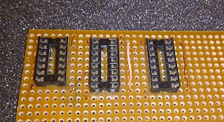
It's taken years to get this good at soldering ;) and naturally without three hands, I managed to solder the first socket in one column of holes the wrong way and the worst way, so one of the link wires is under the small socket, no big deal.

Saturday 2 November 2013

I think I fixed the reset problem

I added a NAND gate to the circuit and put it inline with the enable signal for the pump driver. This prevents the pumps engaging when the controlled is reset.

Something like this:

Wednesday 30 October 2013

Tank connections and 80 micron mesh ordered

To join the tanks I ordered 4 Overflow Tank Connectors 22mm

This has a 22mm thread on it, which is the same as the one that a washing machine uses.

So I ordered some 80 micron stainless steel mesh

after seeing some filters built into 22mm washers for washing machines.

Consequently I have also got some 22mm connection tubing

Tuesday 29 October 2013

Growing tanks acquired

I got a couple of plastic containers to use as growing tanks for an ebb & flow setup from Wilkos. It says £5 there, it said £ on the shelf in the store but at the till they were £3.99

The plan is to pump water from a store into one of them through 10mm pipe and have a 22mm overflow connector feed the second one and another 22mm overflow exit that one and return the water to the store. This means that the containers won't overflow.

A second overflow connector in the bottom of each one container will feed into the solenoid valve I ordered yesterday. This will be activated for the drain cycle to make sure that the water stock is completely removed. The water removed in the drain cycle is filtered through an 80 micron passed into the recycling phase where nutrients and pH are set to appropriate levels and other processing such as uv exposure for removing biological pathogens such as pythium can take place.

Separating the flood store from the recycling phase means that the pH and ppm probes can be utilised across multiple growing areas. The probes are the most expensive parts of the system so this reduces costs when scaled. The UV can also be used across growing areas.

The tanks and connectors in the "grow room"

Monday 28 October 2013

First controlled flow.

I got my first reading from the flow meter. The instructions reminded me to use the pull up resistor. The code is a bit basic.

Octave code for plot
times = [ 66.192 67.180 68.180 69.180 70.180 71.180 71.280 72.180 72.280 73.380 75.180 75.480 76.180 76.580 77.180 77.680 78.080 78.780 79.080 79.880 80.080 80.980 81.800 82.080];
ticks = [ 34 101 105 750 833 836 846 847 862 921 923 942 944 964 967 1018 1021 1072 1075 1132 1137 1196 1200 1266 ] ;
plot(times, ticks);

This isn't the best data but it's late and I want to go to bed. It's supposed to start with a low flow and then get to a steady state, this is to prevent the flow meter being overwhelmed. I'm sure at this flow rate that there is no real danger of that but it was the right idea to start with.
The k-factor is 1120, that is 1120 ticks per litre. Next time I shall see about measuring amounts.

Solenoid valve ordered

I have ordered a normally closed, 240V solenoid valve with 10mm pipe connections - datasheet

The device was £19.99; ex VAT but eventually cost me £31.08 included VAT and delivery.

Sunday 27 October 2013

Making danger

Putting yesterday's bits together. I have the relay gaffer taped into a pop bottle and the pump sitting in a 25 litre bucket. I have checked that the pump runs from energising the relay. All good.

Time to write to code for the NXP. First off for sensor testing purposes is to get the TCP / IP running. The simple UDP sender already found a checksum bug in the supplied library. Oh well, at least the packets still show up in Wireshark. Let's hope TCPSERVER on Linux will ignore it.

Off to Wickes / B&Q now to find some plumbing bits.

Saturday 26 October 2013

Ready to get my feet wet

I bought a 12v relay from Maplin that will switch 240v to power the pump I have with a 10mm outlet. I have wired it all up and tested the switching action. Success. I've put pins on the flow meter (snipped LED legs) and made signal cables for the relay with more pins from an old Nokia power supply that had an inline step-up adapter.

Luckily I had a 3 pin mains socket, they wanted over £ for one in Maplin. Mine still has the 99p sticker from Wilkos.

That means I'm ready to start pumping some water.

Thursday 24 October 2013

Toodle Pip

The PVC tubing has arrived. It is 10mm inside diameter. I should have measured the darn pumps because although they look the same size they are, in fact, 8.5mm diameter. So I ordered some 8mm / 10mm tube which will be here next week. Good news is that it fitted the flow meters, which is the specification I took the measurement from. OOh, I happen to have a 600 L/H submersible pump with a 10mm fitting so I can commence the flow meter testing.

Thursday 17 October 2013

Tuesday 15 October 2013

Plumbing

The flow meter is specced at 3/8" push on fitting so that's a good place to start because the pumps have no specification given.

Having looked it it, it might make sense to think about some clips but lets not spend cash needlessly for now, wait for normal cables ties to fail.

The flow meter also says that it should have a pre-filter for 80 microns, that is 0.08mm. "Mesh 200" is 0.075mm so this size is the most appropriate.
I have found some mesh on ebay which is £2.99 per 15cm x 15cm sheet but there are also various inline ones, a fuel filter for instance but that's £17.99

Monday 14 October 2013

Direct Pump Control Circuits

My going with dumb pump design it means more pins being used on the NXP. However we still have plenty to play with. P5-P30 on the LPC1768 and P5-P36 on the LPC11U24. The LPC1768 has three UART serial connections so I shall reserve two of those for the sensors. So to keep it to common PINS for some reason, P17-20 used for the flow restricted pumps and P5-P7 for the peristaltic pumps.

The peristaltic

The flow controlled

I made a start on the code at http://mbed.org/

For a quick test, I used this code

#include "mbed.h"

DigitalOut myled(LED1);

DigitalOut a1(p5);

int main() {
    while(1) {
        myled = 1;
        a1 = 1;
        wait(0.5);
        myled = 0;
        a1 = 0;
        wait(0.5);
    }
}

to strobe the motor.

The results were satisfying

Sunday 13 October 2013

Peristaltic Pumps

This is a quick knock up circuit I did on http://circuits.io/

The AT-Tiny uses three wires RX, TX & GND to communicate with the controller. The protocol will say which pump 1-4 and how many mL and the At-Tiny will take care of the rest. Just keep the Enable lines up, no need to for anything else as we're not changing direction or anything. I've left off the possible 4th pump as I haven't got one.

Regular pumps with flow meter

Because of varying head heights of the water storage, return from recycling, etc. issues I have chosen to use a flow meter to regulate water input. The idea being that all water input pumps can be pumping together and shut off once the required amount has been delivered. The flow meter introduces an additional complexity because the flow meter instructions say that the water speed should rise gradually and that air should be prevented from enterting the system. My pumps will be submersed so I'm not sure that will be an issue. For this discussuion that's not really an issue because that is a software problem likely to be quite simple by just modualting the control line.

The flow meter produces 1120 pulses per litre and takes a TTL supply voltage.

This circuit activates either pump, watches the flow pulses and then kills all pumps when the required flow is complete.

Smacked in the KISSer

The smart pump idea, although good, is draining time trying to solve a problem I added to the project. As it eating into the schedule I am going to drop that part and just use the one microcontroller. The rest of the design is the same and the control methods are the same. Bringing back the smart pump idea can be done later and swapped in piecemeal.

Specifically I am finding getting the communication between the controllers more difficult than it should be. Debugging two sets of code at once is hard. Especailly without any on chip debugging. It's just "Did that work? No. Next idea" which is not good methodology. Made worse by working in the simulator! I have a new serial port PCI card coming which I need so I can run the newest version of the simulator, although I'm not sure that will solve the immediate problem. At least I will only be typing on one PC!.

Friday 11 October 2013

Deadline is longer than previously thought

haha the 4 week deadline was just for the planning, not the project in total. That's actulkly due on 6th December! That gives me plenty of time to debug the active pump controls.


However, for now I shall continue on the dumb pump mission so at least I will have a working set of pumps and can reduce the pin requirement later.


Last night I managed to kill the £45 LPC11U24 :( so as a backup in case I kill the LPC1768 I ordered the FreeScale KL25Z, which was only £17.20 thus making it an attractive controller


Useful pdf about interrupts and clocks

Found a useful reference for interrupts and clocks with good examples of setting all the bits to get them working properly. Handy if you've not done it for a couple o'years like me.
But watch out, the = print as - in Mozilla PDF reader!

Thursday 10 October 2013

NXP signalling the AVR

I spent an eternity reading PortD instead of PinD. Thank goodness for the power of web searching. Shame everyone programs in C. They are scared of the power.

NXP code


DigitalOut m1(LED1);
DigitalOut m2(LED2);

DigitalInOut DATA(p21);
DigitalInOut CTL(p23);

void set_data(unsigned char i) {
    DATA.write(i);
    m1.write(i);
}

void set_ctl(unsigned char i) {
    CTL.write(i);
    m2.write(i);
}

int main() {
    CTL.output();
    DATA.output();
    
    while(1) {
        set_data(0);
        set_ctl(1);
        wait(3);
        set_data(1);
        set_ctl(0);
        wait(2);
    }
 }

AVR Code

.include "m16def.inc"

; set portB to output
ser r16
out ddrb, r16
clr r16
out portb, r16

; set portD to input with pull-ups
out portd, r16
out ddrd, r16
ser r16
out portd, r16

; do the do
main:
    in r16, pind
    out portb, r16
    rjmp main

Wednesday 9 October 2013

AVR signalling the NXP

The NXP code is pretty basic

#include "mbed.h"

DigitalOut led(LED1);
DigitalIn DATA(p23);

int main() {
    
    while(1) {
        led.write(0);
        while(DATA);
        led.write(1);
        while(!DATA);
    }
}

The AVR code was a bit trickier as it uses the timer interrupt. Took me a while to get my head round it

.include "TN13DEF.INC"

.org 0000   ;  reset interrupt vector
  rjmp on_reset

.org 0012   ;  timer0 overflow interrupt vector
  rjmp tim0_overflow

on_reset:
  ser r16
  out ddrb, r16 ; set the pin I/O

  ldi r16, 0b_0000_0101 ; set the clock multiplier
  out tccr0b, r16

  ldi r16, 0b_0000_010 ; turn the timer on
  out timsk0, r16

  sei ; turn on interrupts

main:
  nop ; I walk and walk, do nothing 
  rjmp main

tim0_overflow:
  ; negate portb
  in r17, portb
  com r17
  out portb, r17
  reti

Getting the AT-Tiny working with the STK500

Fairly simple, follow online instructions.

  1. AT-TINY13 in SCKT3400D1
  2. Connect the ISP6PIN socket to SPROG1 with the 6-pin cable provided
  3. Connect the PORTE/RST to PORTB/PB5 and PORTE/XT1 to PORTB/PB3
  4. Jumpers VTARGET, AREF, RESET, XTAL1, OSCSEL close; others open

Using it is a bit annoying because you have to take the cables on and off to use the pins.

Tuesday 8 October 2013

Decisions Decisions - Smart or Stupid Pumps?

Do I put the control next to the pumps and free up the controller to just send messages or do I keep them dumb and use the controller to do everything ?

The programmer in me wants to put an AT-TINY13 at every pump and let them do the delivery. OTOH guy says put everything in the middle because there's so much spare CPU power.

An AT-Tiny is about £1. It is attractive to me to make intelligent pumps. But it means programming the AVR and whatever I use as the controller and get them to talk to each other. But this also means that the controller can be less powerful and all it needs to do is talk whatever protocol I devise. A rich protocol, which could even be 9p, seems to solve engineering problems. By standardising with this idea I can expand the range of devices in the family as I go along. I will only have to implement the protocol on the central controller once and not care about that is attached to it.
I'm looking for excuses to make smart pumps. The action at the pump end will be the same whatever controller is used, whether it is the central one or not is irrelevant. If I start with AVR assembler to control the pumps I can always use an AVR CPU to do it and they are not rare.
There we go, that is what I shall do.

Time to Propose a Protocol

At the moment I have a 3 wire serial system. 1 GND, one marked TX and one RX. I need to solidify this idea in text, write some code and test it in real hardware. If things don't go well the next option is to add another wire, which I still have space for if I stick to three peristaltic pumps. Which is no problem for this project. L293D's are under £2 each.

After a couple of days cogitating I have made a decision. I considered a variable length with the msb marking another byte like in UTF-8. However this is over complicated for this little job so I have decided on a fixed length scheme.

One possibility.

The minimum number size bound the amount of liquid in millilitres.
1111 1111 1111 1111 is 65535 which is 65.535 litres. This fits the bill for the 30 litres in the specification.
So the protocol, at the moment, is three bytes long
aaaa aaaP - action and parity bit
bbbb bbbb - lower bits of value
cccc cccc - upper bits of value

The next idea

I realised that it is unlikely that a pump will get a 1.01L instruction. They will usually get 10ml or 10L. However there may be the possibility that the controller has a small and large pump on the same L239D. So let's encode the magnitude in the action, I have plenty of those to go round and the amount can just be a single byte.
aaaa aaaP - action and parity bit
vvvv vvvv - value
This is the most satisfying to me. A message will then fit into a 16 bits.

The Protocol v0.1

ActionValueDescription
0000 00001010 1010All Off
0000 0001vvvv vvvvPump 1, v ml
0000 0010vvvv vvvvPump 2, v ml
0000 0100vvvv vvvvPump 3, v ml
0000 1000vvvv vvvvPump 4, v ml
0001 0000vvvv vvvvPump 1, v L
0010 0000vvvv vvvvPump 2, v L
0100 0000vvvv vvvvPump 3, v L
1000 0000vvvv vvvvPump 4, v L
1111 11111010 1010All on until further notice

The values in the All On and All Off are to make sure that a signal is being sent and not just some line noise.

Wednesday 2 October 2013

Aceeed

There are three acids listed in Resh's hydroponic book

  • Nitric acid
  • Sulfuric acid
  • Hydrochloric acid
  • Phosphoric acid

The trouble will be to find a suitable hose that is acid resistant.

The peristaltic pumps come with silicone tubing and for this the news is not so good. Because of that I have included citric acid in the list.

Acid 20 °CPVCSilicone
Nitricup to 50%Maybe - test it
Sulfuric up to 95%No
Hydrochloric50% - concentratedNo
Phosphoricup to 85%Maybe - test it
Citric10% - SaturatedExcellent

It seems a citric acid solution is preferable for my uses.

Saturday 28 September 2013

Taking stock

First task of the day is to take stock in the components bin.

My 200-in-1 electronics kit has a few possibly useful bits

  • 4k:4k transformer
  • 900:8 transformer
  • Quad nand
  • Dual JK Flip-flop
  • 7 seg LED
  • 2 NPN
  • 2 PNP
  • level meter analogue
  • 9v controlled relay - controls 24V DC @ 10A or 12A @ 120V AC or 10A @ 220V DC
Microcontrollers
  • AT Mega 16L - 0633J
  • AT Mega 8515L - 0633
  • 5 x AT TINY13 - datasheet
  • STK500 AVR programmer
  • NXP LPC11U24
  • NXP LPC1768
  • mbed breakout board (unpopulated)
Sensors
  • LIS3LV02DQ Breakout - 3 axis sensor
  • MPU-6050 3 axis & gyro sensor
  • Samsung E700 camera with breakout
  • HMC5883L - Triple Axis Magnetometer Breakout
  • LV Max Sonar EZ1
  • 5 x LM35 precision temp sensor
  • 20 x 3mm photo transistors NPN
  • 2 x minature microphones
ICs
  • SN7415N 4-16 decoder / multiplexer - datasheet
  • 4 x L293D push pull four channel driver for motors - datasheet
  • 4n25 - optocoupler
Output devices
  • Nokia 6100 LCD colour breakout
  • 2 x TEC1 - 12709 peltier
  • 12V solenoid
  • 50ish superbright white LEDs
  • 9 x 3mm red LEDs
  • CIRRUS CS225/STD 6g MICRO SERVO
Discrete bits
  • 4x BC547B - NPN transistor
  • 2x BC548B - NPN transistor
  • 1x BC549C transistor
  • 2k trim pot
  • 2 x 5v zener diode
  • TIP127 linear switching darlington PNP transistor
  • Less than 50 100nF caps (43 i think)
  • 1x 50v 4.7 uF electrolytic cap
  • plenty of resistors, descriptions to follow

Friday 27 September 2013

End of Week One

At college today. Wrote a project spec and some other documentation.

Spent session two re-reading "Serial Port Complete" - Jan Axelson

This evening I read the MODSERIAL code and other serial libraries on http://mbed.org/

Found sources on ebay for MAX232 TTL/RS232 converters in case I need them, including RS232<>USB - although looking at the Atlas-Scientific page, they output 0-5v rather than +- 12v so I won't need a convertor

Did a cursory search for funding opportunities for Urban Sustainable Development projects - which is what this project to be the first step towards a full blown urban renewal project through hydroponic growing, using renewable energy sources to run HIDs when the sun don't shine, preferably a water mill.

Read deeper into Reverse Osmosis water purification techniques. Although not strictly part of the specification, RO water is preferred to raw tap water and also facilitates the use of rain / river / waste domestic water in a hydroponic system. Also by passing spent water through an RO unit it can be released safely into the environment which might be more convenient than re-using it as an input. Especially good for funding applications: a farm that produces drinking water as well as food from sea / river water or at least one that outputs waste water that is cleaner than it arrived. The RO most suitable to the starter operation is the M500P-UV which is £259 and can produce 189 litres per day, and consumable filters per year of £29.95 + £54.95 + £24.95 = £109.85

Subsequently read on and discovered that if you source your RO from the tap, lots of water >50% is not filtered at all and discharged to wherever your "waste" pipe goes, along with any precipitate. So it's better for filtering a source such as a stream or sea water but not already potable water.

Wednesday 25 September 2013

My Lucky Day

Ordered the flow meter from RS, in fact, I got two.

And I ordered the peristaltic pumps from cpc.farnell for £82.62 sigh

I also ordered the three regular pumps which came to £17.64

I went all in and ordered the sensors too: conductivity £142.944 inc VAT and pH £91.50 inc VAT

A total of: £334.70 for which I worked 54 hours.

Saturday 21 September 2013

Project Week 1

I had given the project some thought but to get a concrete idea I created a block diagram design.

We had covered flow sensors in last year's sensor section. The I/O units would be gravity fed valves. The idea being that the valve opens and the the fluid runs until sufficient has been detected by the flow meter.
Upon researching the valves I discovered that gravity fed valves are the not the normal method. The simplest devices use the pressure of the fluid to open the diaphragm, such as this one from Adafruit and only £6. Valves that open with 0 pressure are called latched valves or zero pressure valves and are slightly more expensive, starting at about £25. Here's a selection of all kinds.

The second issue is that the ultrasonic flow meters I knew about are £187 each which is prohibitively expensive when I need at least 6 of them. So I considered using the same flow meter for each input.

This is a possible configuration. It does rely on the flow meter being sensitive.
I found one for 0.5-15 l/m at RS; it uses a rotary mechanism.

The next option I considered is one without a flow meter but instead uses timed delivery. This has been the stalwart of liquid delivery systems.

For accuracy I investigated peristalic pumps which seem a reasonable compromise at about £30

Before I make any decisions I need to estimate the actual volumes of fluid for each input because I anticipate needing a range of accuracy /control for each input rather than homogenous.

Ok I need something like 10ml of feed per 10 litres of water for both Solutions A and B. The Adafruit pump does 100 mL/min so 6 seconds is 10 mL. Of course I could pre-dilute it so if I did it 50/50 that 12 seconds is the same 10mL concentration but I'd have to mix 20 Litres of output.

So, in conclusion, I need three peristalic pumps to add solution and pH fixer. The water input pump, output pump and also the recycler pump can be the 9L/min pump and use a "cheap" flow meter.

This leaves me with the following block diagram: